If you’ve ever added aftermarket tire sizes on your vehicle, you might have noticed that your speedometer is no longer accurate. I had this issue and wanted a unique functional way to measure my real speed. I saw a friend with a Game Boy shell that had a GPS speedometer and decided I needed one.
There were a couple people selling these already, but I wanted to make my own and now I’d like to share with you how I did it. This guide walks you through the process I use, including necessary supplies, step-by-step instructions, and estimated costs of the supplies and tools that I use.
As I mentioned, these are good for people running aftermarket tire sizes. However, they are also useful for those who have JDM imported vehicles with km/h dash clusters, or even people who simply want a cool retro accessory in their car. Let’s jump right in.
Materials and Tools
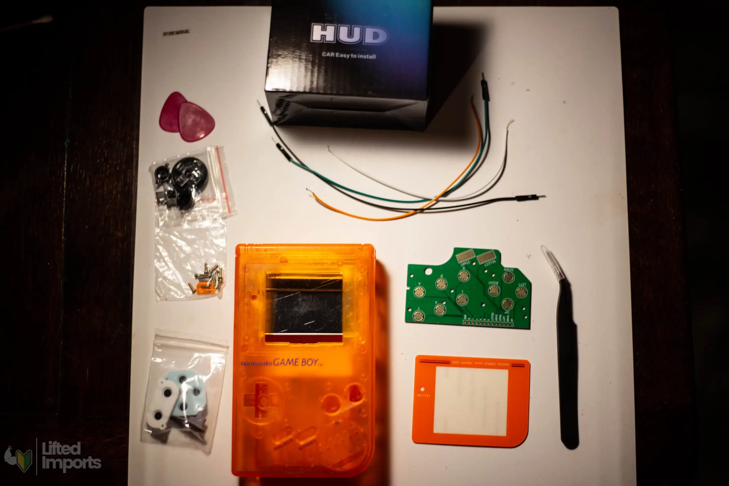
Before you start, gather the following supplies and tools. You can find these on Amazon, and Ebay. But I also shop at Hand Held Legend if I want some exclusive premium Gameboy parts. They typically cost a bit more, but they occasionally have shells and buttons in colors that I haven’t found anywhere else. Their shipping is also pretty quick and not terribly expensive.
Here is a small gallery of the majority of supplies that you’ll need:
Step-by-Step Instructions
Components $55-80 Total Cost:
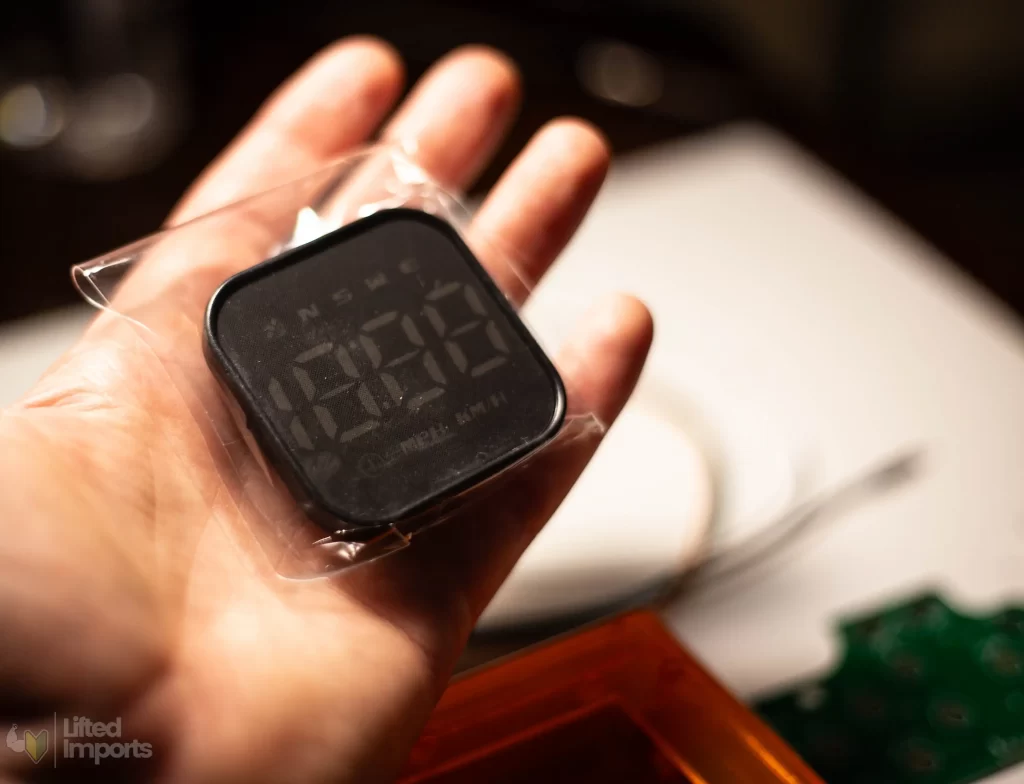
GPS Speedometer Module – $20-$25
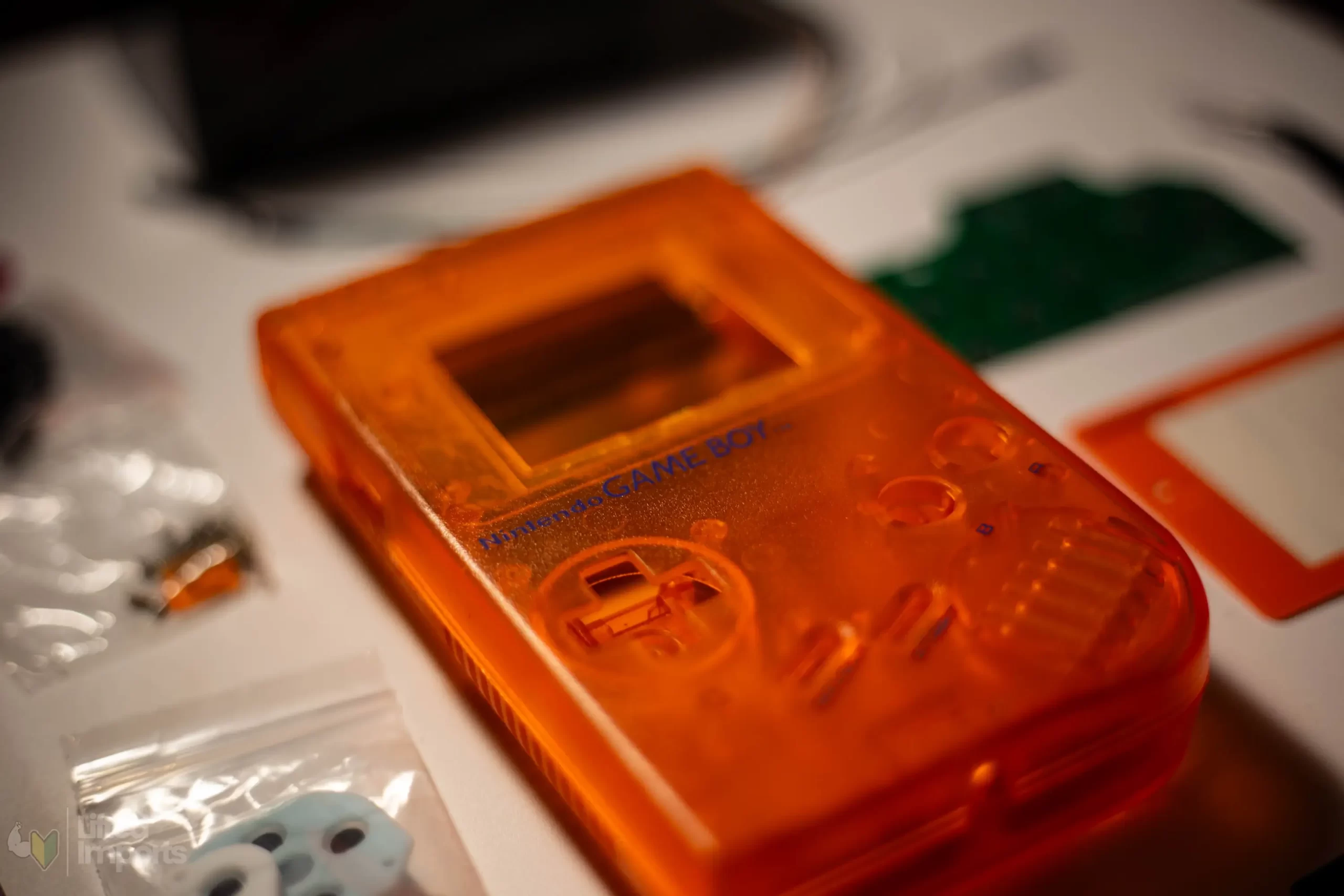
Game Boy Shell– $15-$25
Replacement Screen Lens (Optional) – $5
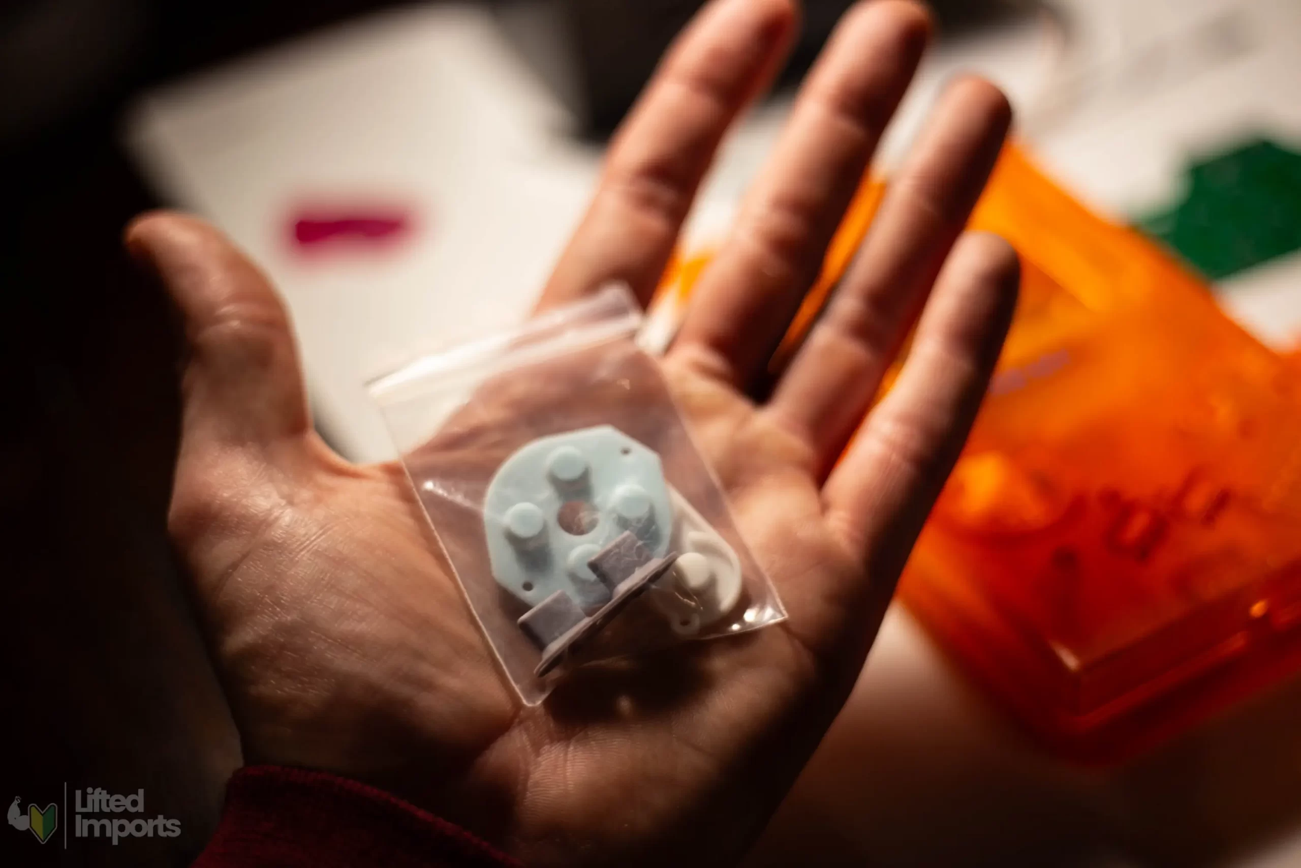
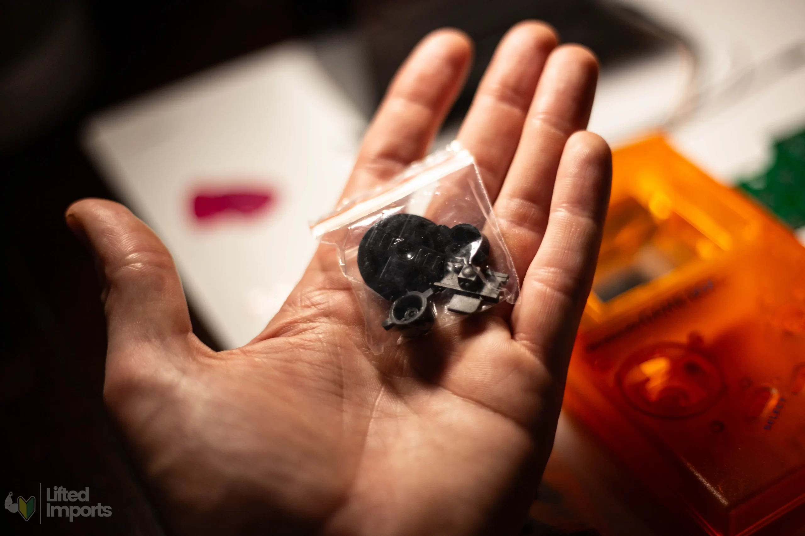
Button Set (May Not Be Needed If Shell Includes Them) – $5
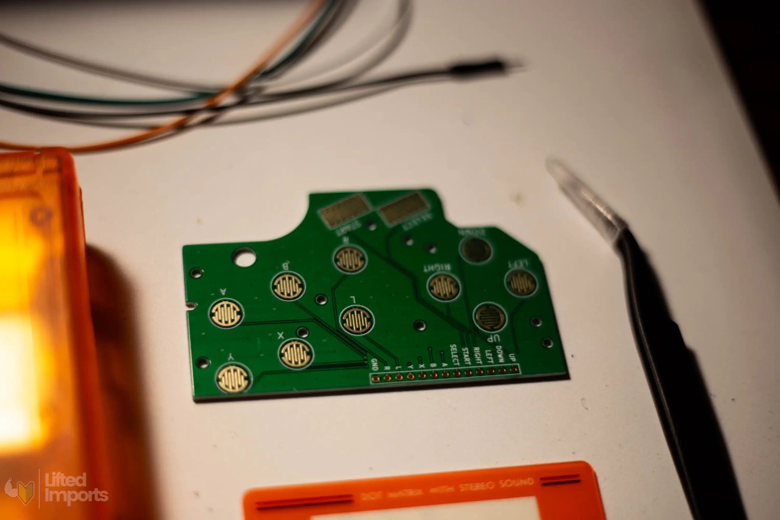
Printed Circuit Board (PCB) for Buttons – $10-$15
Small Gauge Wire – $5-$10
Tools Approximately $65-$150 Total Cost:
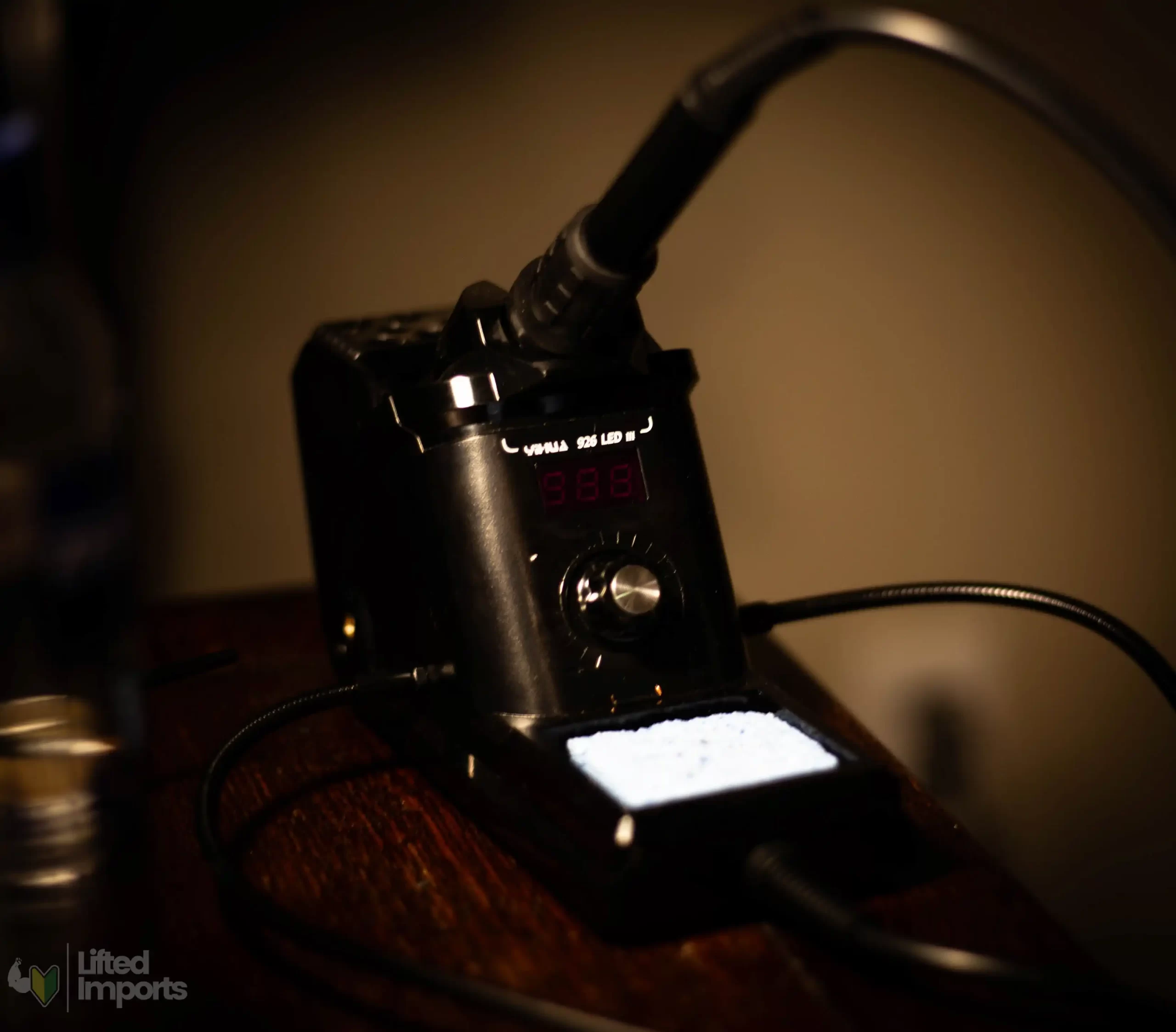
Soldering Iron (Adjustable Heat Settings Is Extremely Helpful) – $20-$60
Soldering Wire – $5
Dremel or Rotary Cutting Tool– $25-$50
Masking Tape – $2
Guitar Picks (for prying open GPS casing) – $1-2
Hot Glue Gun & Surebonder Brand Glue Sticks – $10-$20
Air Blower Tool (for dust removal) – $5
Step 1: Testing the GPS Module
Before modifying anything, test the GPS speedometer module by plugging it in and ensuring it connects to satellites. This is best done outdoors for optimal signal reception. This is vital because you will be modifying the GPS and if you do this only to find out it was defective from the factory, you won’t be able to initiate a return.
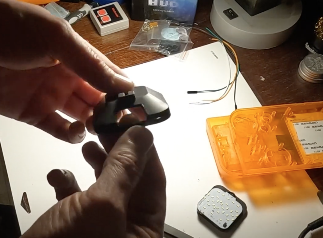
Once testing is complete, you can begin pulling the plastic casing off of the GPS unit using guitar picks (I use smooth finish guitar picks instead of textured or matte picks for easier insertion.)
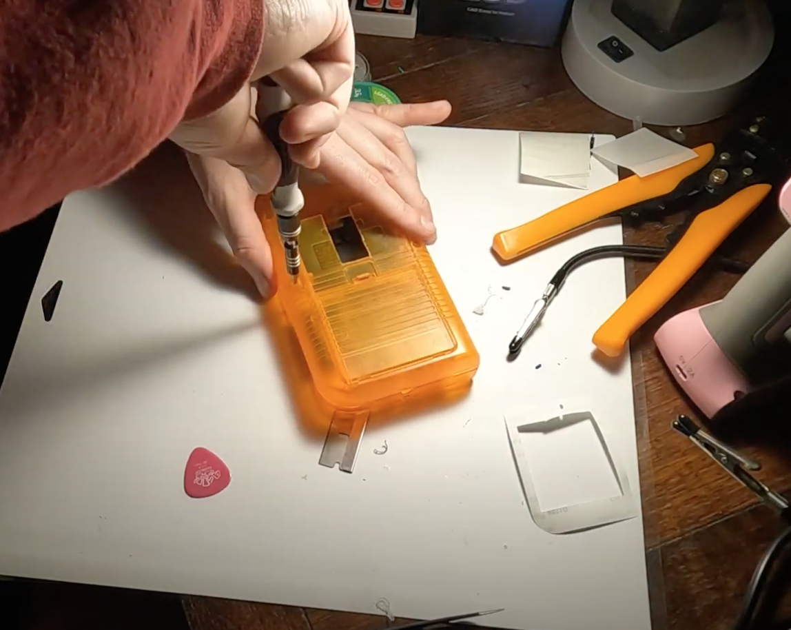
Step 2: Preparing the Game Boy Shell
Disassemble the Shell – Use an electronics screwdriver kit to remove the metal bracket inside the Gameboy shell.
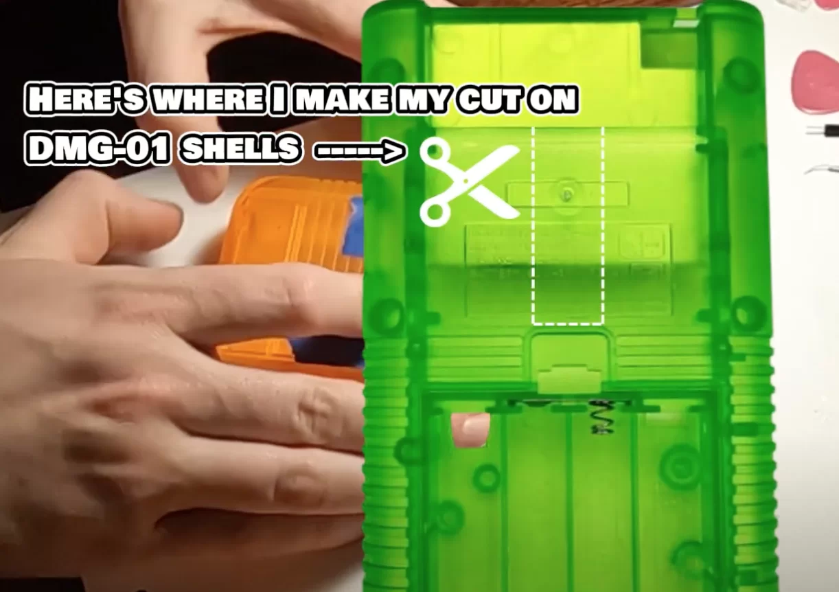
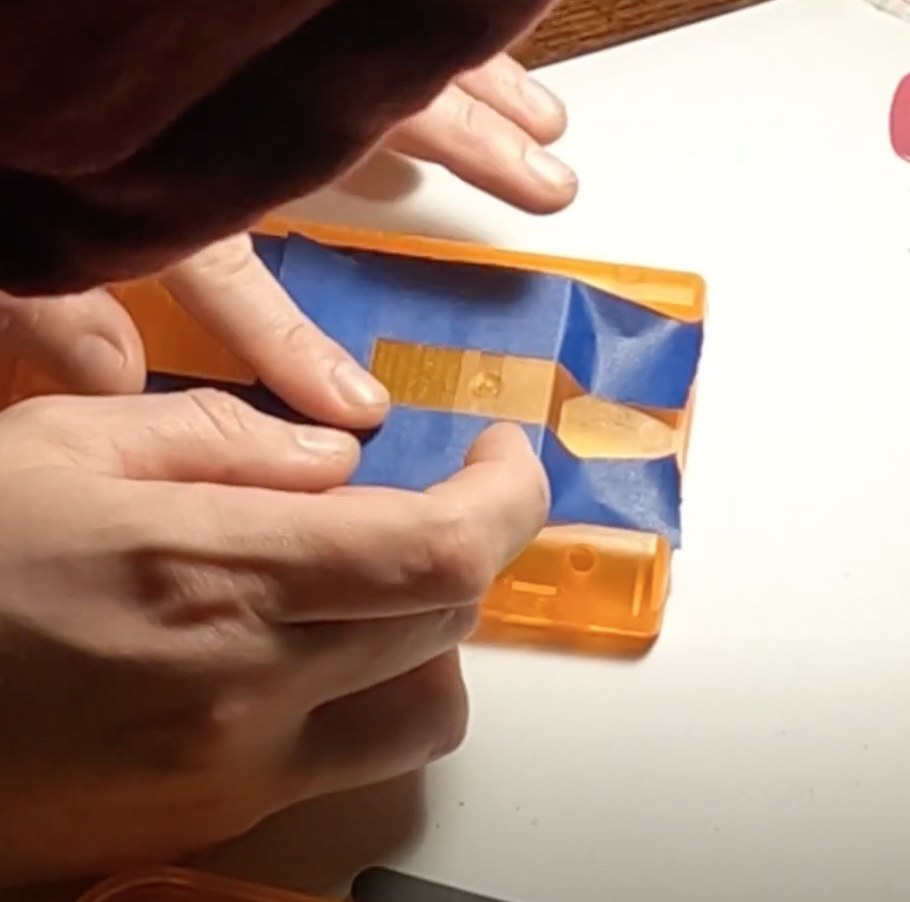
Mark Openings – Apply masking tape to the back of the shell, aligning it with the battery door latch.
Drill Guide Holes – Drill small holes at the corners of the where the cutout will be to create cleaner cuts with the rotary tool.
Begin Cutting – Use a Dremel to cut the necessary openings for the GPS unit and suction mount. I make sure the shell is in a secure position typically in a clamp or vice and I always use safety glasses when cutting.
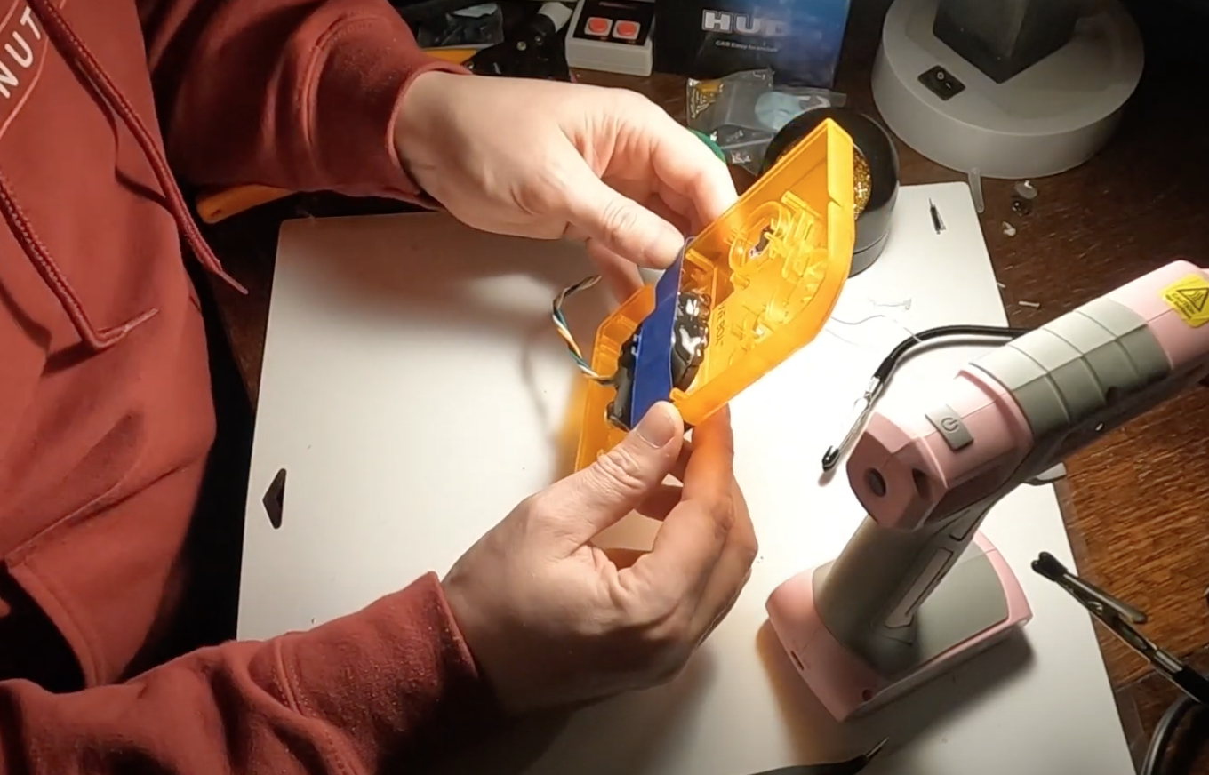
Trim The GPS Shell – The GPS cap will need to be trimmed back to fit the wiring through. In Gameboy Color shells, the entire front of the GPS cap will need to be trimmed down almost flush with the circuit board to fit inside the shell.
Step 3: Wiring the Buttons
Expose Contact Points – I use a razor blade to remove plastic from around contact points on the GPS unit. This will allow you to get a clear shot at the metal as you place the wire on it.
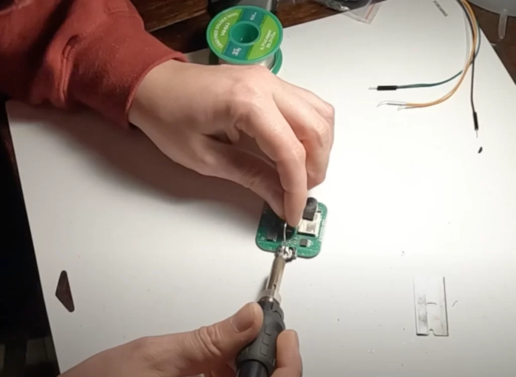
Prep the Wires – Strip and tin the wires before soldering them to the contacts for left, right, down, and ground functions.
Begin the Soldering Process – Carefully solder the wires to the GPS unit contacts.
Route the Wires – Guide the wires through the Game Boy casing where you want them, ensuring that there will be clearance when you reassemble. You can either do this now or after you complete the button PCB wiring.
Label Everything & Finish Soldering to PCB – Use a notes app or tape to label each wire for correct soldering position on the button PCB. The PCB will have labeled through-hole points to solder into.
Step 4: Installing the GPS Unit
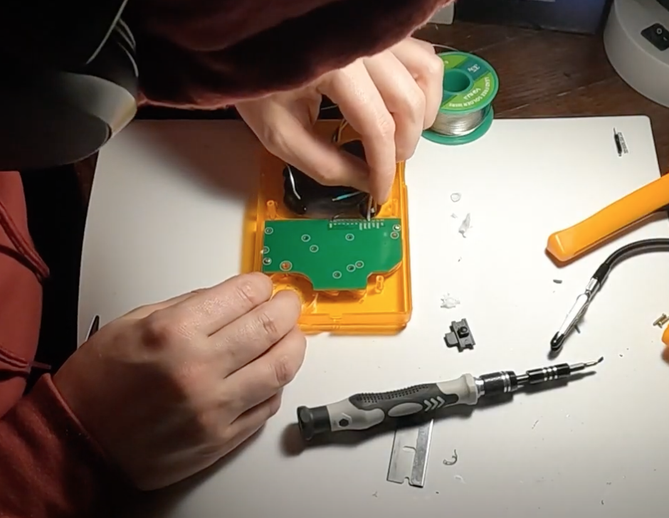
Secure the GPS Unit – Place the GPS module inside the shell and tape it into position with masking tape.
Prepare the Mounting Surface – I lightly scuff the sides of the GPS unit and the inside of the Game Boy shell with sandpaper to help glue adhesion.
Glue in Place – I use Surebonder glue sticks with a hot glue gun to attach the GPS unit. The Surebonder brand seems to be the best option that I’ve found so far. Initially, I make 3 or 4 smaller applications with the glue. Then I let it dry before removing the tape and fully gluing the unit into place. Be careful with application if using a transparent shell for a clean finish. When I’m doing a clear shell, I take extra care to not make a globby mess with it. But with solid color shells, you can be a little more carefree with how the glue looks.
Secure Button Circuit Board – Once the GPS unit is installed and the button board is connected to it, the final mounting of the button PCB can begin.
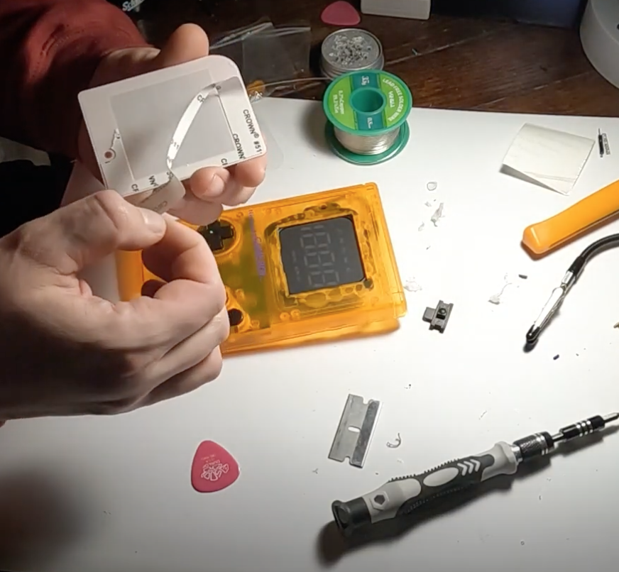
Step 5: Final Assembly
Test the Connections – Before closing the case, I always power on the GPS module again and confirm functionality. It’s much better to discover any issues at this point than after full reassembly.
Reassemble the Game Boy – Insert button membranes and buttons, secure the PCB, and place the screen lens into position.
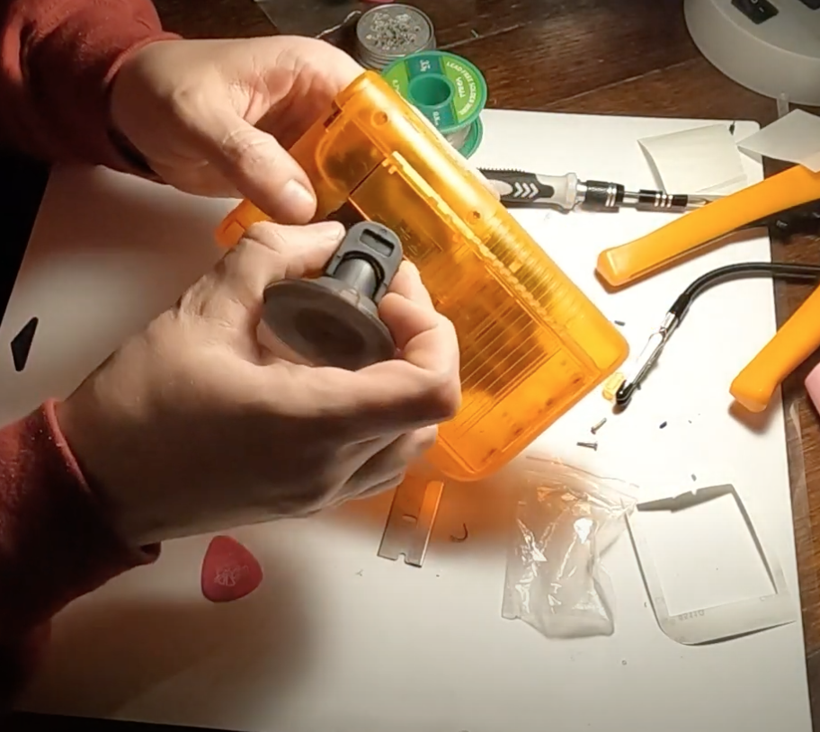
Attach the Suction Mount – Ensure proper fitment and secure attachment for stability in a vehicle. I’m always careful when installing the suction mount to avoid snapping the stem that holds it.
Step 6: Final Checks
-
Power On and Test – Confirm that the GPS is tracking speed accurately. If needed use menu option 1 to fine tune the speed reading.
-
Remove Protective Film – Clean and remove any protective coverings for a polished look.
By following these steps, you’ll have a fully functional Game Boy speedometer ready to mount in your vehicle. I recommend taking extra care to not leave the Gameboy in direct sunlight for long periods of time during hot weather. Extreme heat can warp the Gameboy lens, possibly deform the case, and weaken the glue inside.
This project combines retro nostalgia from my childhood with modern tech, creating a unique gadget that always starts conversations. If you plan to build more, consider experimenting with different casings, GPS modules, and mounting options. I really enjoy the process of building these.
If doing this project seems a little daunting or something you don’t care to do, we offer them for sale right here on the site. We can build a wide range of color options for you. Check out our online store here: Shop Gameboy Speedometers